What's COG Display?
Abstract
For industrial, automotive, and portable equipment designers,Chip-on-Glass (COG) liquidcrystal display (LCD) modules offer many advantages compared to traditional LCD modules with a packaged LCD driver. This white paper compares COG modules to conventional LCD modules,showing the key differences between the two, and explaining why COG modules are thinner,have greater reliability, offer flexible design, and are more cost effective.
Introduction
• LCDs are often supplied as LCD modules which have built-in driver circuitry that simplifies installation and improves reliability. However, the addition of packaged driver circuitry in LCD modules also results in a number of disadvantages because it:
◇ Increases the thickness of the display
◇ Raises the costs
◇ Creates greater vulnerability for failures of the modules
• All of these drawbacks are important considerations when it comes to displays for industrial, automotive and portable equipment. That’s whydesigners in these areas should strongly consider using Chip-on-Glass (COG) LCD modules. Chip-on-Glass (COG) LCD modules offer a very thin profile, enhanced reliability, and a reasonable price.
The Chip-on-Glass Concept
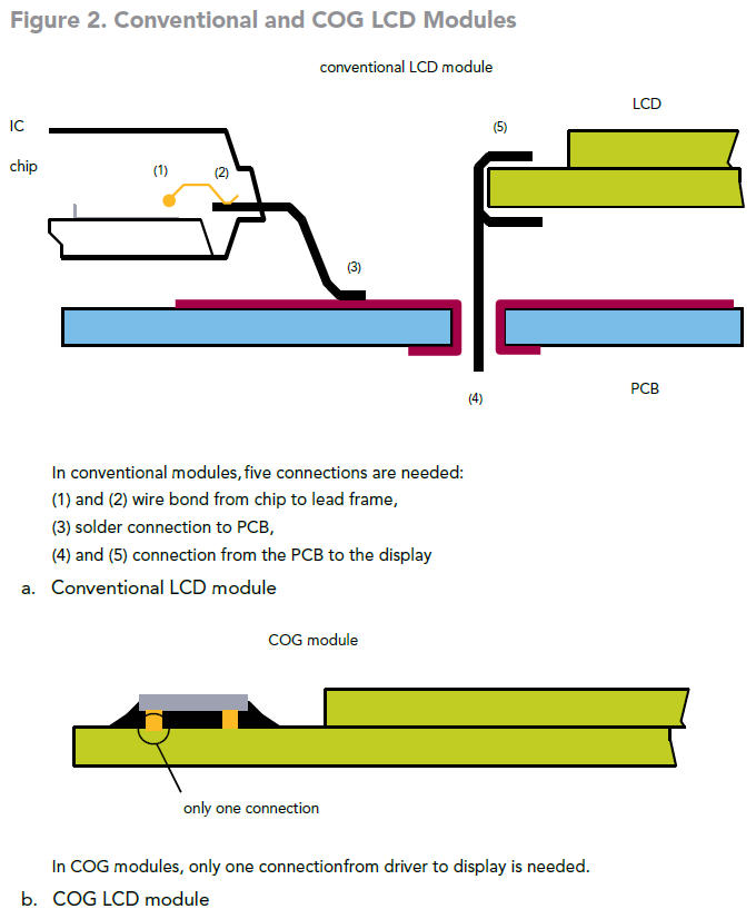
• In a conventional LCD module, the LCD driver is mounted on a PCB at the rear of the module. This more than doubles the overall thickness of the display. The drive connection is made using either fixed pins or elastomer connectors. For the connectors, several bonds are required for every drive input to the LCD.And because LCDs generally require many drive inputs (even when multiplex drive techniques are used),the quality of these bonds is a critical factor in determining reliability.
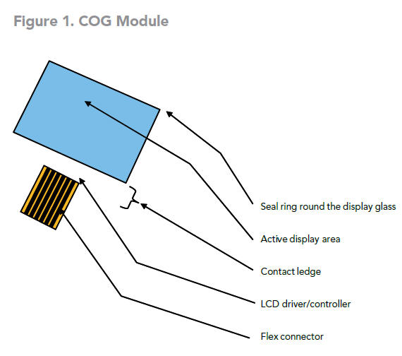
• In comparison, COG modules have the LCD driver mounted directly on an overlapping edge of one of the glass plates that make up the LCD. The resulting module is an integrated display, less than 3 mm thick,with all connections from the LCD driver to the LCD completely isolated from the environment. With COG modules, each connection requires only one bond, which ensures optimal reliability of the module.
An Inside Look at Chip-on-Glass Manufacturing
• LCD Cell Production
◇ In a COG module, one of the two glass plates that make up the LCD is extended to make room for an LCD driver to be mounted and connected. As with conventional LCDs, ITO (Indium Tin Oxide) electrode patterns are created on the surface of the glass plates. In COG LCDs, these patterns are extended to include a connector track for the LCD driver. In addition, an external connector is also used at the edge.
◇ For reliable operation, the resistivity of the connector tracks to the LCD driver must be lower than the resistivity of the ITO connections used within a conventional LCD cell. To enable ACF bonding technology,the LCD drivers are produced with gold bumps on the connecting pads. The connections between the LCD driver and the interface connector are also formed by ITO, with wide tracks recommended for low impedance. The tracks to the display can be of higher impedance, but for ideal balance, they should beroughly the same impedance (all rows, all columns).
Chip Bonding with Anisotropic Conductive Film (ACF)
• For Chip-on-Glass manufacturing, three components are required: LCD cell, LCD driver and the ACF(connecting media), as shown in Figure 3.
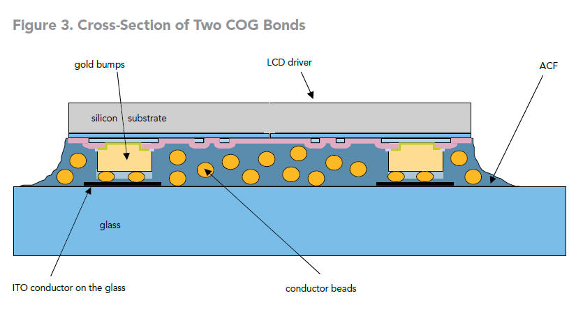
◇ The ACF consists of an epoxy (similar to UV curable glue) containing electric conductor beads.
◇ The conductor beads assure contact between the gold bumps of the LCD driver and the ITO conductors on the glass. Curing of the ACF glue establishes the necessary pressure between the chip and the glass to ensure a good electrical connection between the bumps and the tracks on the glass.Roughly 30 beads per bump guarantee reliable contact.
◇ Due to the surface tensions of the glue on the conductor beads, there will be no horizontal contactbetween the beads, thereby avoiding short circuits between neighboring gold bumps of the LCD driver.
COG Supports Many Design Options
Another benefit of COG technology is that it supportsa broad range of display designs, with few limitations:
• The placement of the LCD driver can be on any side of the active display area. This allows optimal use of available space around the display (for example, to attach switches).
• Any type of liquid crystal technology can be used:
◇ TN: LCDs using Twisted Nematic (TN) technology produce black pixels and characters against a clear background. Ideal for multiplex rates up to 1:8.
◇ STN: Super Twisted Nematic (STN) technology is used for displays requiring a high multiplex rate.This technology provides a high-contrast display with a wide viewing angle.
◇ ABN: Displays with Advanced Black Nematic(ABN) technology provide very high contrast ratios with true black pixels and characters, wide viewing angles and only a slight temperature-dependent performance and color shift.
• COG technology allows the cascading of LCD drivers to enlarge the number of display elements (pixels).
• One of the few limitations of COG technology is that only LCD drivers with gold-bump contacts can be used.
Illumination
The rear-side display polarizer has a reflective coating to match the required illumination mode:
• Reflective mode: A continuous reflective coating allows viewing in ambient light
• Transmissive mode: The back polarizer is left clear and the display must be illuminated from behind
• Transflective mode: A thin reflective coating offers sufficient reflection for viewing by ambient light and allows backlighting to shine through, so the display can be used in dim conditions.
For transmissive and transflective mode displays, the following backlighting systems can be used:
• LED: Several LEDs are mounted in a flat (3 mm to 4 mm deep) box that includes a light guide which distributes the light evenly over the display. LED backlights are available in many colors and produce a bright display when supplied with a low DC current. They have a very long lifetime of up to 1,000,000 hours.
• EL panel: A phosphor-impregnated sheet that provides very even illumination when supplied with AC voltage
(typically 100 V (RMS) at 600 Hz). EL panels have a very thin profile but are not as bright as LED backlights and draw more current. They have a typical lifetime of 2,000 hours.
• Incandescent lamp: A low cost, but rather bulky,illumination system can be created using conventional light bulbs. The display must be carefully designed to avoid uneven illumination.
Connectors
The tracks leading to the edge of the glass allow the COG module to be connected to a microcontroller. Several methods can be used to enable this connection:
• Flexfoil: Fixed directly on the glass with a hermetically sealed bond. Flexfoil offers a highly reliable and flexible
connection system.
• Fixed pins: Clipped to the edge of the glass, fixed with conductive glue and sealed with epoxy, fixed pins offer a very stable and low-cost connection method that is recommended for most applications. The pins can be soldered directly to a PCB or fitted to a suitable interface connector.
• Glued-on connector: Glued directly to the edge of the glass and protected by a plastic housing, this type of connector offers an alternative, low-cost solution.
Side-by-Side Comparison of LCD Module Manufacturing Methods
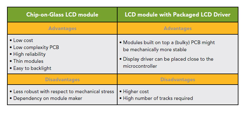
Compared to LCD modules with a packaged LCD driver, COG modules offer major benefits with onlyvery few disadvantages for equipment designs as shown in the table below:
Side-by-Side Comparison of LCD Module Manufacturing Methods
Industrial, automotive, and portable equipment designers should strongly consider utilizing COG LCD modules for their LCD needs. COG modules are considerably thinner, more reliable, flexible, and more cost effective than traditional LCD modules with a packaged LCD driver.
For COG modules, go to https://www.buydisplay.com/graphic-display
The information below is required for social login
Sign In
Create New Account